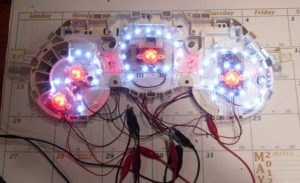
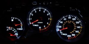
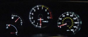
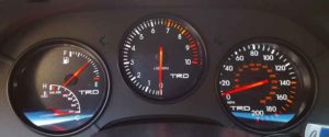
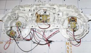
I had originally installed the basic #194 and #74 LED bulbs into the stock bulb sockets which did an initial job, but it wasn’t perfect: like here which looks like this. This is what the cluster looked like after installing just the LED drop ins. It still had some greenish hue. I found out that Toyota puts a coating on the back of the gauge faces. After a year, I decided to take the whole assembly apart and line the inside with NLFS Cool White thin strips LEDs. This is what they look like inside. Here is the wiring from the back. I ran all the 12V and ground thru the vents and tied then together. The I ran just 1 red wire for the + and 1 black wire for the -. The green copper paths are very thin and canbe scraped away to expose bare copper for a solder pad. I used 26 ga wire. I installed all the LED strips onto the Illumination circuit paths. Or what controls the stock bulb sockets. These do dim quite well with the stock rheostat.
But this still left inconsistent lighting because of the coatings on the back of the gauge faces. So the next step, which took me forever to decide, was remove all the needles and take all the gauge faces off and sand the coatings off. But….before I did this, I needed to find away to re-install the needles in there correct position. So I built a cheap 555 timer circuit. A 555 timer circuit is a very simple $10 thing. Just a single 555 chip, and a few passive parts. You can get all at a Radio Shack. I used this design . You will note that I wrote specific resistance values associated with the RPM or SPEED in case you don’t have a scope. Although a decent Voltmeter can read frequency, which is all you need to verify needle positions.
So with this, I connected the 555 timer to the pins of the gauges and marked where they were based on the imputed frequency. Pretty much all 6 cyl engines put out 50HZ per 1000RPMs and 11HZ per 10MPH. Once I had the needles positioned I noted the specific resistance so later i wouldn’t need the potentiometer.(R2). For the Coolant, that just uses a resistance. So I found that a 220 ohm resistor put the needle dean on the low temp tick mark as shown here. The fuel was simple, just fill the car up totally full and replace the needle at the full position. Now, knowing exactly how the gauges work. All of the gauges have a 12v+ and Ground. They all have a 3rd connection. That is what I call the “source signal”. Which for the Tach, is the Igniter, speedometer is speed sensor, fuel is the in-tank “sender” and the coolant, well it is the coolant sensor on the engine block. All of these are found on the back of the cluster. Here is the back of the cluster showing the specific pin-outs. The Power and Ground for all the gauges is pins # B 7 & 9. The “source signal” comes from harness B for Fuel, Coolant, and Tach and Harness A for Speed.
This schematic will somewhat help if you can read it. Note where to put the 220 ohm resistor for the temp gauge.
So the next step after removing everthing is to sand off the crap on the back of all the gauges. I followed the directions from another SF member and sanded with 600 wet/dry then 1000 wet/dry to uncover the numbers. Prior to sanding, you cannot see any of the face numbers since they are hidden by this coating.
Here is what they look like after sanding.
So I finish this whole retro, install everything, calibrate the needles and it is WAY to bright. Easy fix, I install a 100 ohm resistor to the power feed to the back of the cluster. But, even though it looks fantastic, the red needles damn near disappear. So I am forced to take everything back apart and install custom made red LED needle brightners. This is pain staking to say the least.
Red Needle recepticle (-Obsolete-Replaced with NEW Circuit Boards
Installed onto plastic Diffuser (- Replaced with above Micro Circuit Boards
Back Side Wiring (- Notice sanded backs removing light film blocker
Front w/o the needle (- You can see the 3 Micro Red LEDs shining through.
So HERE is the new cluster with LED strips with OUT the red needles accentuated.
This HERE is “after” the red needles done. Now the cluster looks like a new 21st Century dash~!
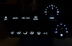
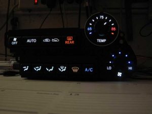
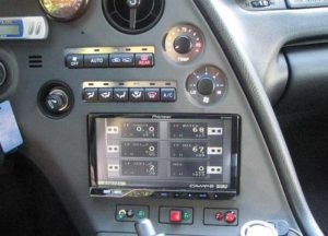
New In-car CLUSTER and HVAC Pictures. Notice the Silver HVAC overlays.
